
🖨️ From Scripts to a Session#
For a long time, my AI-assisted 3D printing workflow went like this: describe the part in a prompt, get back an OpenSCAD script, render it, squint at the preview, ask for a tweak, get back another script. It worked (plenty of my printed parts started life exactly that way), but every round trip was effectively a one-shot: the agent wrote code blind, I rendered it, and whatever it had “learned” about the part vanished the moment the chat moved on.
I’ve since moved to a different setup: instead of generating OpenSCAD text, an agent drives an actual FreeCAD session directly, through an MCP server. It sees the model, edits it, checks it, and saves it: the same way a person would sit at the keyboard, except it can also retain a lot more context about the printer, the tolerances, and the hardware on hand than I can be bothered to.
This post is about that second setup: how to structure a project folder for it, and what a sound baseline configuration file looks like.
🧩 Why the Switch Was Worth It#
A few specific differences between “AI writes OpenSCAD” and “AI operates FreeCAD via MCP”:
- A genuine session, not a text pipe. The agent can open the document, look at it from any angle, change a dimension, and instantly see the result, instead of regenerating a whole script and re-rendering from scratch for every change.
- A parametric model outlasts the conversation. The output is an actual
.FCStddocument with labeled parts and a dimension table, not a wall of generated code that only makes sense alongside the chat that produced it. You can open it afterward, by hand, and it still makes sense. - State can endure across sessions. A small set of plain Markdown files (printer profile, learned tolerances, hardware on hand, lessons from past prints) give the agent a memory that OpenSCAD scripts never had. Printed something too snug? That feeds back into a file, and the next part benefits from it automatically.
- Verification occurs before anything gets sliced. Checking that a shape is a valid solid, that two parts don’t overlap, that a screw stack really reaches its nut, is a line of Python in the running session, not a visual gut check on a rendered preview.
None of this is about FreeCAD being “better” than OpenSCAD as a CAD engine. It’s about giving the agent a durable, inspectable workspace instead of a prompt-in, script-out loop.
📎 A Concrete Example#
A recent case: a height-adjustable desk sits against a wall, and instead of just leaning against it, it should glide up and down along a wall-mounted rail. The plan was a 20x20 mm V-slot aluminum extrusion bolted to the wall, with a roller carriage already riding that profile, carrying a 3D-printed clamp that grips the underside of the desktop.
Before any printed part got designed, the two things that already existed physically went into the FreeCAD document as plain reference geometry: the extrusion profile and the carriage’s mounting plate, modeled at their real dimensions, plus the tabletop as a semi-transparent reference plane at its measured thickness.
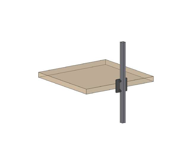
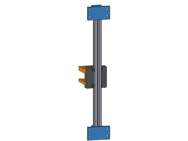
Everything else got built around that: two wall brackets at the top and bottom of the profile, and a printed clamp that bolts to the carriage’s existing mounting holes and grips the tabletop edge with a jaw tightened by a bolt and an embedded nut, so it doesn’t damage the wood.
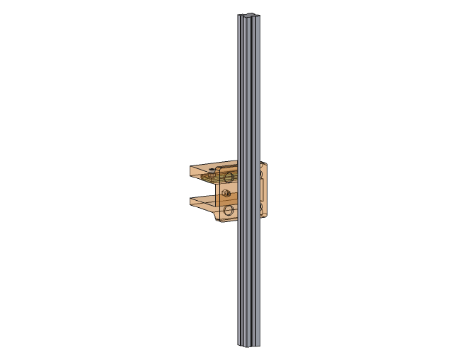
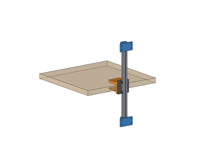
Having the carriage and profile as real geometry in the document, not just numbers in a prompt, made checking the design as direct as building it: does the clamp’s bolt pattern line up with the carriage’s actual holes, does the jaw clear the profile as the carriage slides, is there still enough wall thickness in the printed part where a screw passes through. All of that got checked against shapes sitting right there in the session, not against a written spec.
🗂️ Setting Up the Workflow#
The setup itself is pleasantly low-tech:
- Choose a root folder for your projects, e.g.
~/3d-prints/, with one subfolder per part you design. - Place an
AGENTS.mdfile at the root.AGENTS.mdis a plain-Markdown convention that most agentic coding tools already pick up without any extra setup, regardless of which one you use, rather than a file tied to one specific product. That matters here because the entire point is a durable, tool-agnostic project setup. - Confirm a FreeCAD MCP server is running and reachable. MCP (Model Context Protocol) is the standard that allows an agent to call into an application (in this case, a running FreeCAD instance) instead of just generating text. A few open-source MCP servers for FreeCAD are available; pick one, start it, and point your agent’s tool configuration at it. I use neka-nat/freecad-mcp, whose README covers installing both the FreeCAD addon and the server itself.
- Launch your agent inside that root folder. Most agentic coding tools automatically load
AGENTS.mdfrom the current directory on startup, which means the printer profile, tolerances, and workflow rules are already in context before you’ve typed a single word.
From there, every new part is simply a new subfolder, and every session starts already knowing how you work.
📝 What Belongs in AGENTS.md#
Approach the file like onboarding notes for a new colleague: everything the agent would otherwise have to re-derive or ask about every single time belongs here, and nothing that’s one-off project state does. A sensible split:
AGENTS.mditself contains the workflow rules: how to model, verify, and export.- A small
profile/folder next to it holds the learned state (printer characteristics, current tolerances, hardware on hand, and lessons from past prints), so the rules inAGENTS.mdstay steady while the knowledge underneath keeps growing.
Here’s a pared-down but complete example, generalized from a working setup:
# AGENTS.md: FDM 3D printing in FreeCAD via MCP

This folder is for parts designed to be 3D printed (FDM). Each part gets its
own subfolder. Before designing anything, read the profile below; it holds
what's already been learned about this printer and should be treated as the
source of truth, not generic defaults from the internet.

## 1. Load the profile first

- `profile/printer.md`: printer, nozzle size, slicer/process defaults,
  filaments in use.
- `profile/tolerances.md`: current clearances and fits, each with a status
  (confirmed / in use / untested) and a short history of how it got there.
- `profile/hardware.md`: screws, nuts and inserts on hand. Design around
  what's already in stock before asking for a trip to the hardware store.
- `profile/lessons.md`: design and process lessons from earlier parts.

## 2. Model in FreeCAD via its MCP server

- Check that the MCP server is reachable before doing anything else. If it
  isn't, ask whether to start it; don't fall back to writing a standalone
  script instead.
- One FreeCAD document per part, saved as `<subfolder>/<part-name>.FCStd`.
  Save after every meaningful change, not just at the end.
- Put every dimension that might reasonably change into a `Params`
  spreadsheet (name, value with units, short description), and bind the
  geometry to it with expressions. A clearance or hole spacing should be
  changeable in one place.
- Name objects by what they are (`bracket_body`, `screw_boss_M3`,
  `clip_arm_left`), not by creation order.
- Reuse existing parts by opening their `.FCStd` and copying the shapes you
  need, instead of starting from a blank document every time.

## 3. Design for printing, not just for geometry

- Pick the print orientation as part of the design, not after. It decides
  which faces need supports and which loads run along layer lines versus
  across them (layers separate more easily under tension).
- Prefer splitting a part into simpler pieces joined by hardware over one
  complex part that needs heavy supports, unless there's a specific reason
  (strength, a single-piece requirement) not to.
- Only use filament other than the default PLA when the part actually needs
  it: functional fits and snap/press mechanisms, heat exposure, outdoor use,
  or large flat panels prone to warping. State the assumption if you don't
  ask.

## 4. Verify before exporting

Check this with code against the actual geometry, not by eyeballing a
screenshot:

- every solid is valid and is a single solid (unless it's meant to be more
  than one);
- parts meant to stay separate don't overlap, and print-in-place parts have
  exactly the clearance the profile specifies;
- moving parts clear their full range of motion;
- screw stacks: head seat, grip length, nut engagement, no unintended
  protrusion;
- the part fits the printer's bed in its print orientation.

## 5. Export

- STL, one file per printed part, already in print orientation. Print-in-
  place assemblies go into a single STL with each piece already placed.
- If you're revising a part that was already printed, move the previous
  files into a subfolder named after what changed (e.g. `v2-tighter-snap/`)
  instead of overwriting them.
- Report print settings only where they differ from the profile defaults:
  orientation, supports (or why none are needed), wall/infill overrides for
  load-bearing features, and any fit used, with its status from the profile.

## 6. Feed print results back into the profile

When a printed part is reported back ("too loose", "snapped at the
corner", "fits perfectly"):

1. Identify which value in `profile/tolerances.md` it corresponds to.
2. Log the result with date, part, material, and the outcome in that file's
   history section.
3. Adjust the current value accordingly, and update its status: a single
   good fit is enough to mark it confirmed, but keep track of which material
   it was confirmed in.
4. Anything that isn't a number (a design approach that worked or didn't)
   goes into `profile/lessons.md` instead.

Keep the profile short and current: the top of each file is the current
truth, the history below it is the evidence for why.
Swap in your own printer, materials, and hardware once the structure is in place: the point of the file is the workflow it encodes, not the exact numbers inside it.
🧠 Final Thoughts#
The biggest change isn’t really “FreeCAD instead of OpenSCAD.” It’s that the agent now has a workspace with memory, not a loop that generates text and forgets it. The MCP server makes that possible on the technical side. AGENTS.md and a small profile folder are what let you pick the session back up tomorrow, on a totally different part, without starting over on your printer.
If you’re still at the “describe it, get a script back” stage, that’s a fine place to be, and it still gets you printed parts. But once you want the second part to build on what you learned from the first, you need a session that remembers. Not a prompt that forgets.
Got your own agent + CAD setup, or questions about the MCP side of this? Glad to compare notes.