
⚡ Why These Switches?#
Let’s be honest: retrofitting light switches in an existing home is a pain. Chiseling into walls, pulling cables, patching holes, sanding, painting — all to move a switch 1.5 meters to the left because your desk happens to be right there now? No thanks.
That’s why I chose kinetic RF switches over the usual suspects like WiFi or battery-powered ones. These things are completely wireless, battery-free, and powered by pure button-press energy. Yeah — like the spark-click on a gas lighter, except instead of igniting propane, it triggers an RF signal.
It’s brilliant. One press of the switch generates enough energy via a piezo element to power a tiny circuit and transmit an RF code. No wiring. No batteries to change. No waste. And even better: the included receiver module can pair with up to five different switches.
In short, it solves three big problems at once:
- No digging up walls
- No drained batteries to replace (or throw away)
- No need to compromise on switch location ever again
Naturally, I had to hack it.
🛠️ What I Did#
I wanted full integration into my Home Assistant setup via MQTT, which meant figuring out how the switch talks — and then talking back.
Step 1: Spectrum Analysis with URH#
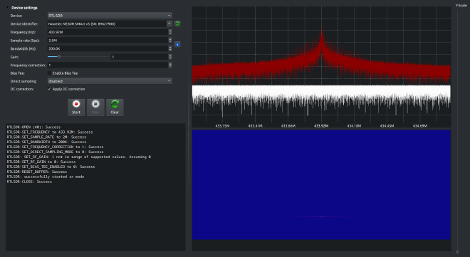
First, I plugged in my Nooelec RTL-SDR v5 (a USB software-defined radio stick) and fired up Universal Radio Hacker (URH). URH is a complete suite for wireless protocol investigation with native support for many SDRs. It makes demodulation easy, automatically detects modulation parameters, and helps visualize the bits and bytes flying through the air.
To begin, I opened the Spectrum Analyzer inside URH and pressed the kinetic switch while watching for spikes in the RF spectrum.
Boom — a clean burst every time I clicked. Frequency locked in: 433.92 MHz.
Step 2: Recording the Signal#
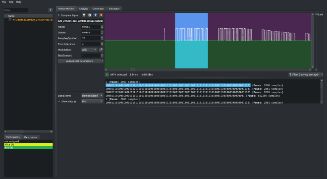
Now that I had the frequency, I switched over to URH’s “Record Signal” mode. I hit record, pressed the switch a couple of times, and voilà — beautiful bursts of modulated data.
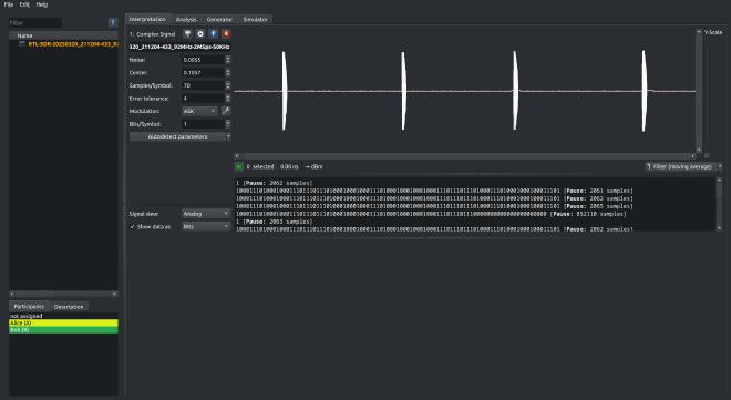
In the screenshot above, you can see four distinct signals — I pressed the switch four times, and each press resulted in a burst of RF data, clearly visible in the recording.
URH did its magic and automatically identified the modulation as ASK (Amplitude Shift Keying). This actually surprised me a bit — I originally expected FSK (Frequency Shift Keying), which is more common in low-power devices because it can be more energy efficient in noisy environments. But in this case: ASK it is.
🔍 Quick Modulation Primer: ASK vs. FSK#
ASK (Amplitude Shift Keying): Bits are transmitted by varying the amplitude of the signal — a full wave might mean
1, no wave means0.FSK (Frequency Shift Keying): Bits are represented by changes in frequency — for example, a slightly higher frequency might represent a
1, and a lower one a0.
While ASK is simpler to implement, it’s often more susceptible to noise and can be slightly less efficient when every bit counts (literally). Still, it has a smaller circuit footprint — which might explain the design choice here, since the transmission is very short and the goal is simplicity over range.
Step 2.5: Zooming In – Repeating Patterns#
When zooming into a single one of those bursts, a really interesting detail becomes clear: Each press actually transmits the same data multiple times in quick succession — specifically, four times, with short pauses in between.
This is probably done for reliability — in case one of the packets gets lost or garbled, the receiver has a few more chances to catch it.
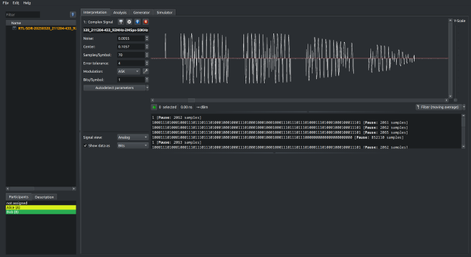
However, at the fourth transmission inside the burst, you can see the signal abruptly cuts off early — it seems like the kinetic module ran out of energy toward the end of the press. So the last repetition is incomplete and would likely be ignored by the receiver.
Still, three out of four fully sent packets is solid for a battery-less button powered by a tiny mechanical click.
Step 3: Demodulating and Extracting Bits#
Next, I demodulated the data. The result was a clean bitstream representing the transmission.
From there, I could copy the binary string and use it later in my ESP code to replicate the signal exactly.
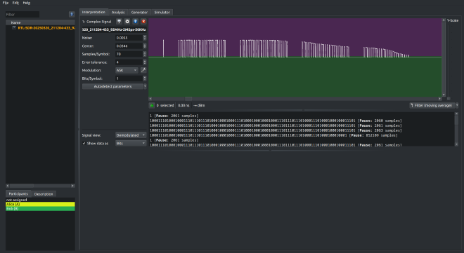
One feature in URH that really helped me during this process is how it highlights the demodulated portion of the signal live as you select the corresponding bits in the panel below. You can literally see where each burst of binary data sits inside the waveform, making it much easier to understand repeat patterns, signal boundaries, and structure.
Now here’s the fun part — and by “fun,” I mean the part that stole more hours of my life than I’d like to publicly admit. 😅
At first, I assumed that the leading 1 followed by a long chain of zeroes was some sort of preamble or initialization pulse — you know, just some fluff before the actual data. And I thought the final 1 was a nice little stop bit. How neat, right?
Wrong.
Turns out, that 1 is actually the first bit of the actual message, and that last 1? Yeah, that’s already the start of the next transmission.
Once I realized this, everything finally made sense.
Each signal follows a structure like this:
1followed by 31 zeros → This seems to be a fixed header (32 bits, or 4 bytes)- Then comes 96 bits of data (12 bytes)
- And the last 24 bits (3 bytes) were the same across all three kinetic switches I tested
So it’s a 4-byte header, a 12-byte payload, and a 3-byte footer, repeated four times per click. Suddenly the protocol was no longer a mystery — it was clean, compact, and weirdly elegant.
And I might’ve cheered a little when the whole thing finally clicked into place.
Step 4: Transmitting It Myself#
Now it was time to go from eavesdropper to impersonator.
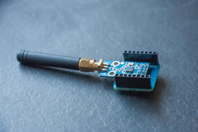
I wired up a CC1101 RF module to an ESP8266 and wrote a firmware that could:
- Connect to WiFi and MQTT
- Listen for MQTT commands
- Transmit the recorded bitstream on 433.92 MHz
The switch I used is this one: Link to the product
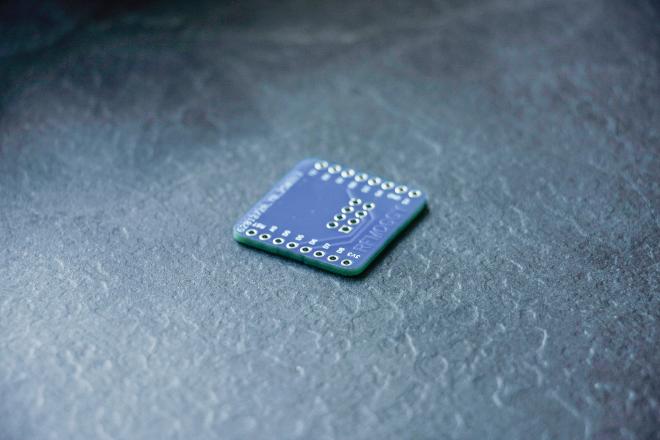
🧩 Handy Hardware: The CC1101 Shield#
To make wiring simple and solid, I used this CC1101 Shield for Wemos D1 Mini. It’s a small PCB that stacks neatly onto the D1 Mini and routes everything correctly for the CC1101 — no jumper spaghetti, no guesswork.
I just grabbed the Gerber files from the GitHub repo, sent them off to my favorite board house, and soldered it up. Worked perfectly on the first try. Gotta love when hardware actually cooperates.
Highly recommended if you’re doing any 433 MHz work with the D1 Mini.
📸 The Setup in a Nutshell#
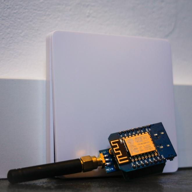
It’s a great example of bridging old-school RF tech with modern smart home platforms — and it doesn’t even require you to tear up your walls.
💻 Code Sneak Peek#
Here’s the firmware I used to make it all work. It’s built on the ESP8266, uses IotWebConf for easy config via captive portal, and PubSubClient for MQTT messaging. Plus a bit of bit-level wizardry to fire off the signal in raw mode via the CC1101 module.
#include <Arduino.h>
#include <ELECHOUSE_CC1101_SRC_DRV.h>
#include <IotWebConf.h>
#include <IotWebConfUsing.h>
#include <PubSubClient.h>
#include <string.h>
#include <DNSServer.h>
#include <ESP8266WiFi.h>

// IotWebConf configuration
#define CONFIG_PARAM_MAX_LEN 128
#define CONFIG_VERSION "mqt2"
#define CONFIG_PIN 4  // D2 (config button/pin)
#define STATUS_PIN 16 // D0 (status LED)

const char deviceName[] = "redected";
const char apPassword[] = "redacted";

// MQTT configuration parameters
char mqttServerValue[CONFIG_PARAM_MAX_LEN];
char mqttUserNameValue[CONFIG_PARAM_MAX_LEN];
char mqttUserPasswordValue[CONFIG_PARAM_MAX_LEN];
char mqttTopicValue[CONFIG_PARAM_MAX_LEN];

// Set up DNS, web server, and MQTT client for IotWebConf
DNSServer dnsServer;
WebServer server(80);
WiFiClient net;
PubSubClient mqttClient(net);

// Set up IotWebConf and configuration parameter groups
IotWebConf iotWebConf(deviceName, &dnsServer, &server, apPassword, CONFIG_VERSION);
IotWebConfParameterGroup mqttGroup = IotWebConfParameterGroup("mqtt", "MQTT configuration");
IotWebConfTextParameter mqttServerParam = IotWebConfTextParameter("MQTT server", "mqttServer", mqttServerValue, CONFIG_PARAM_MAX_LEN);
IotWebConfTextParameter mqttUserNameParam = IotWebConfTextParameter("MQTT user", "mqttUser", mqttUserNameValue, CONFIG_PARAM_MAX_LEN);
IotWebConfPasswordParameter mqttUserPasswordParam = IotWebConfPasswordParameter("MQTT password", "mqttPass", mqttUserPasswordValue, CONFIG_PARAM_MAX_LEN);
IotWebConfTextParameter mqttTopicParam = IotWebConfTextParameter("MQTT Topic", "mqttTopic", mqttTopicValue, CONFIG_PARAM_MAX_LEN);

// Flag for scheduling a reset after configuration change
bool needReset = false;

// MQTT command topic (set after configuration is loaded)
String commandTopic;

// CC1101 configuration
#define GDO0_Pin 5 // Use GDO0 on pin 5

// Predefined binary message for first signal as a string of '0's and '1's
const char *binaryMessage = "10000000000000000000000000000000100010001000111011101110100011101000100011101110100011101000111010001000100011101000100010001110";

// Buffers to hold the packed data and their lengths
uint8_t dataBuffer[128];
int dataLength = 0;

// Converts a binary string ("0" and "1") to packed bytes (MSB-first)
int binaryStringToBytes(const char *binStr, uint8_t *output)
{
  int len = strlen(binStr);
  int byteCount = (len + 7) / 8;
  memset(output, 0, byteCount);
  for (int i = 0; i < len; i++)
  {
    int byteIndex = i / 8;
    int bitIndex = 7 - (i % 8);
    if (binStr[i] == '1')
    {
      output[byteIndex] |= (1 << bitIndex);
    }
  }
  return byteCount;
}

// Minimal raw transmission using the CC1101 TX FIFO.
void sendRawData(uint8_t *txBuffer, uint8_t size)
{
  ELECHOUSE_cc1101.SpiWriteBurstReg(CC1101_TXFIFO, txBuffer, size);
  ELECHOUSE_cc1101.SpiStrobe(CC1101_SIDLE);
  ELECHOUSE_cc1101.SpiStrobe(CC1101_STX);
  // Wait for the transmission to complete using GDO0 as an indicator.
  while (!digitalRead(GDO0_Pin))
  {
    yield();
  }
  while (digitalRead(GDO0_Pin))
  {
    yield();
  }
  ELECHOUSE_cc1101.SpiStrobe(CC1101_SFTX);
}

// MQTT callback: when a message is received, check the command and trigger the corresponding transmission.
void mqttCallback(char *topic, byte *payload, unsigned int length)
{
  Serial.print("MQTT message received on topic: ");
  Serial.println(topic);

  // Convert payload to a String
  String message;
  for (unsigned int i = 0; i < length; i++)
  {
    message += (char)payload[i];
  }
  Serial.print("Message: ");
  Serial.println(message);

  // Check for command and trigger the first signal transmission.
  if (String(topic) == commandTopic)
  {
    if (message == "transmit_01")
    {
      Serial.println("Transmitting first signal via CC1101...");
      sendRawData(dataBuffer, dataLength);
    }
    else
    {
      Serial.println("Unknown command received.");
    }
  }
}

// Called when configuration is saved via the captive portal; schedules a reboot.
void configSaved()
{
  Serial.println("Configuration was updated.");
  needReset = true;
}

// Validate the IotWebConf configuration form.
bool formValidator(iotwebconf::WebRequestWrapper *webRequestWrapper)
{
  Serial.println("Validating form.");
  bool valid = true;

  int l = webRequestWrapper->arg(mqttServerParam.getId()).length();
  if (l < 3)
  {
    mqttServerParam.errorMessage = "Please provide at least 3 characters!";
    valid = false;
  }

  l = webRequestWrapper->arg(mqttUserNameParam.getId()).length();
  if (l < 1)
  {
    mqttUserNameParam.errorMessage = "Please provide a username!";
    valid = false;
  }

  l = webRequestWrapper->arg(mqttUserPasswordParam.getId()).length();
  if (l < 1)
  {
    mqttUserPasswordParam.errorMessage = "Please provide a password!";
    valid = false;
  }

  l = webRequestWrapper->arg(mqttTopicParam.getId()).length();
  if (l < 3)
  {
    mqttTopicParam.errorMessage = "Please provide at least 3 characters!";
    valid = false;
  }

  return valid;
}

// Attempt to connect to the MQTT broker and subscribe to the command topic.
void connectMqtt()
{
  Serial.print("Attempting MQTT connection...");
  String clientId = iotWebConf.getThingName();
  clientId += "-";
  clientId += String(random(0xffff), HEX);
  // Use the username and password for MQTT authentication.
  if (mqttClient.connect(clientId.c_str(), mqttUserNameValue, mqttUserPasswordValue))
  {
    Serial.println(" connected");
    // Publish connection announcement on a status topic.
    String statusTopic = String(mqttTopicValue) + "/status/connection";
    mqttClient.publish(statusTopic.c_str(), "connected");

    // Define and subscribe to the command topic.
    commandTopic = String(mqttTopicValue) + "/command";
    mqttClient.subscribe(commandTopic.c_str());
    Serial.print("Subscribed to command topic: ");
    Serial.println(commandTopic);
  }
  else
  {
    Serial.print(" failed, state: ");
    Serial.println(mqttClient.state());
    delay(5000);
  }
}

void setup()
{
  Serial.begin(115200);
  delay(500);

  // Convert the binary string into packed bytes.
  dataLength = binaryStringToBytes(binaryMessage, dataBuffer);
  Serial.print("First signal data length (bytes): ");
  Serial.println(dataLength);

  // Initialize the CC1101 module.
  if (!ELECHOUSE_cc1101.getCC1101())
  {
    Serial.println("CC1101 Connection Error!");
    while (1)
    {
      delay(1000);
    }
  }
  Serial.println("CC1101 Connection OK");

  ELECHOUSE_cc1101.Init();
  pinMode(GDO0_Pin, INPUT);
  ELECHOUSE_cc1101.setGDO0(GDO0_Pin);
  ELECHOUSE_cc1101.setCCMode(1);                       // Advanced/raw mode
  ELECHOUSE_cc1101.setModulation(2);                   // ASK (OOK)
  ELECHOUSE_cc1101.setMHZ(433.92);                     // Frequency (adjust as needed)
  ELECHOUSE_cc1101.setSyncMode(0);                     // Disable sync word
  ELECHOUSE_cc1101.setCrc(0);                          // Disable CRC
  ELECHOUSE_cc1101.setDRate(30);                       // Data rate in kbps
  ELECHOUSE_cc1101.SpiWriteReg(CC1101_PKTCTRL0, 0x00); // Disable preamble/sync/length
  Serial.println("TX Mode Initialized. Ready to transmit.");

  // Initialize IotWebConf (captive portal and configuration)
  pinMode(CONFIG_PIN, INPUT_PULLUP);
  iotWebConf.setStatusPin(STATUS_PIN);
  iotWebConf.setConfigPin(CONFIG_PIN);
  mqttGroup.addItem(&mqttServerParam);
  mqttGroup.addItem(&mqttUserNameParam);
  mqttGroup.addItem(&mqttUserPasswordParam);
  mqttGroup.addItem(&mqttTopicParam);
  iotWebConf.addParameterGroup(&mqttGroup);
  iotWebConf.setConfigSavedCallback(&configSaved);
  iotWebConf.setFormValidator(&formValidator);

  bool validConfig = iotWebConf.init();
  if (!validConfig)
  {
    // Clear saved configuration if it is invalid.
    mqttServerValue[0] = '\0';
    mqttUserNameValue[0] = '\0';
    mqttUserPasswordValue[0] = '\0';
    mqttTopicValue[0] = '\0';
  }

  // Disable AP timeout so the captive portal is always available when needed.
  iotWebConf.setApTimeoutMs(0);

  server.on("/", []()
            { iotWebConf.handleConfig(); });
  server.onNotFound([]()
                    { iotWebConf.handleNotFound(); });

  // Set up MQTT client with the configured server and our callback.
  mqttClient.setServer(mqttServerValue, 1883);
  mqttClient.setCallback(mqttCallback);
}

void loop()
{
  iotWebConf.doLoop();

  if (needReset)
  {
    Serial.println("Rebooting after 1 second.");
    iotWebConf.delay(1000);
    ESP.restart();
  }

  // If WiFi is connected and MQTT is not, try to connect to the broker.
  if ((iotWebConf.getState() == iotwebconf::OnLine) && !mqttClient.connected())
  {
    connectMqtt();
  }
  mqttClient.loop();
}